If an edge already has a fillet applied the radius of the fillet is used as the bend radius for the new sheet metal part.
Solidworks convert to sheet metal greyed out.
This video shows the difference between creating a sheet metal part from scratch and converting a solid part to sheet metal.
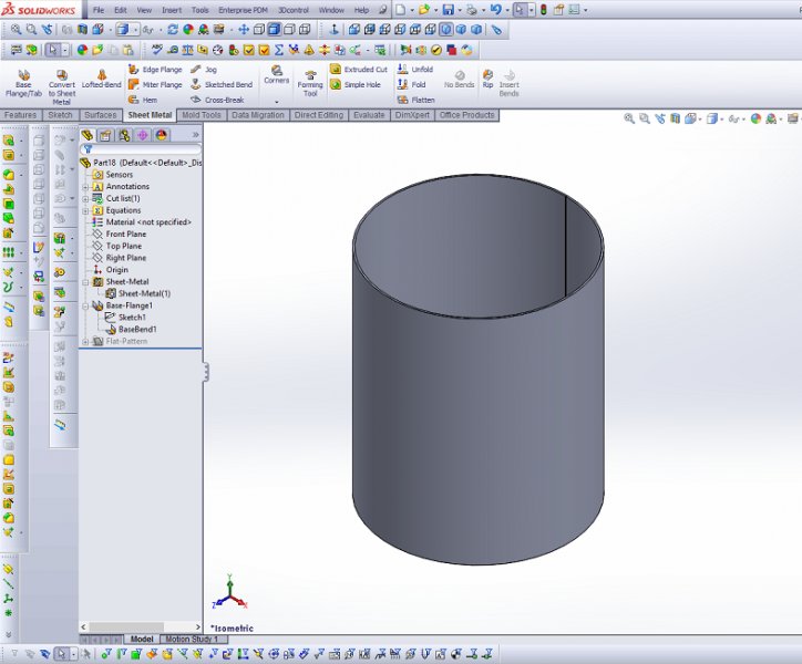
Solidworks convert to sheet metal cylinder.
In this lesson you create the sheet metal part.
As shown in figure 4 the checkbox for keep body has been enabled in order to reuse the same body in case the bottom and back side need to be utilized for a multibody sheet metal design.
Click convert to sheet metal sheet metal toolbar or insert sheet metal convert to sheet metal.
Create the solid part.
Extend the gap into the bend area.
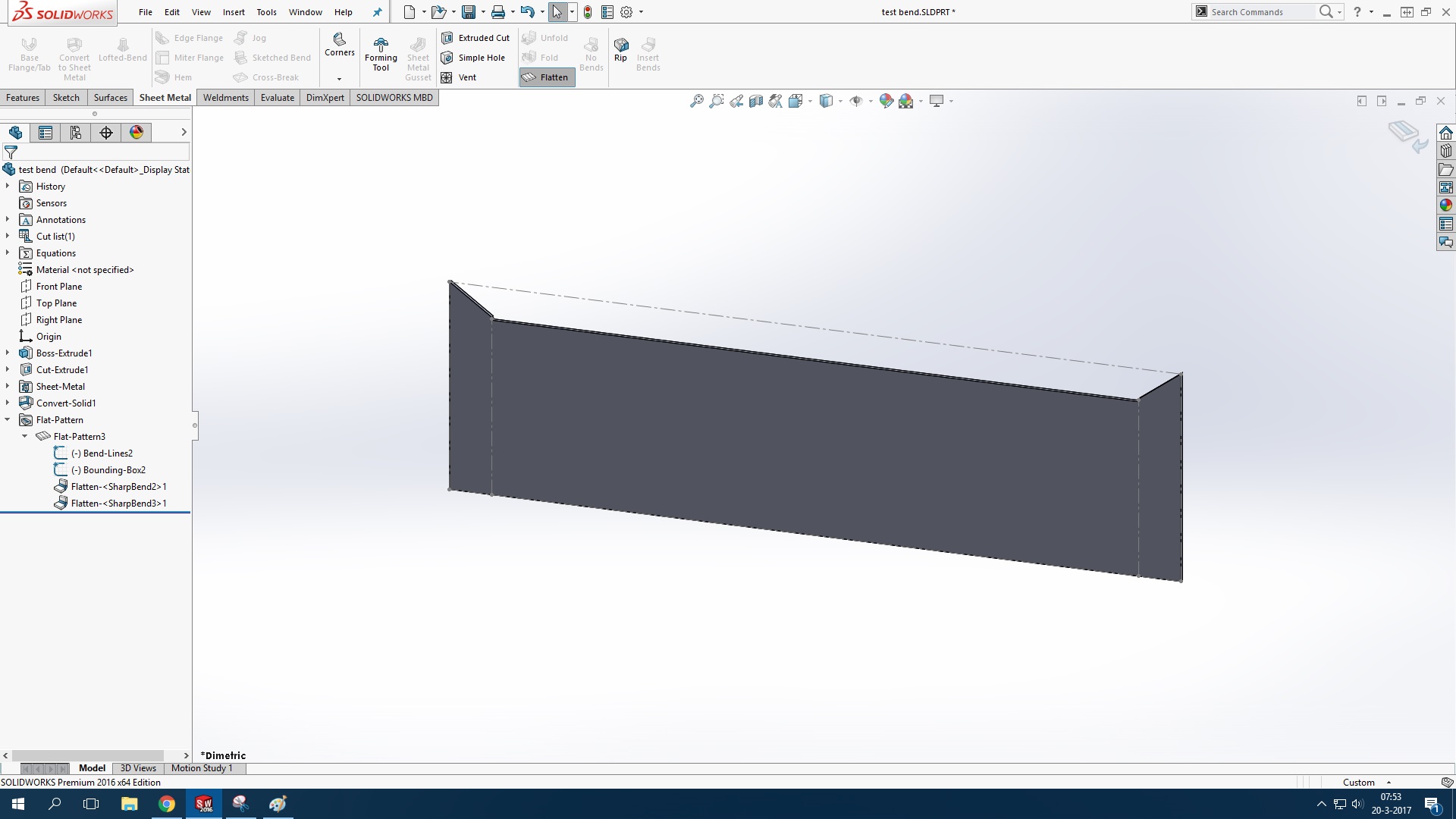
Convert to sheet metal with split line to control one flange.
In the propertymanager under sheet metal gauges set options if you want to use a gauge table.
The software automatically selects the edges on which rips are applied.
How to convert 3d part into sheet metal in solidworks with the help of convert to sheet metal tools.
Leaves the gap unchanged.
For more information about solid.
Select use gauge table.
This tutorial shows how to convert cylindrical hollow solid part to sheet metal cylinder.
Designers are not limited to only one sheet metal part.
1 creating a base flange 2 adding a miter flange 3 mirroring the part and creating.
Please subscribe our channel for more videos and project.
In the convert to sheet metal propertymanager you specify the fixed face and thickness of the sheet metal part the default bend radius and the edges or fillet faces on which to create bends.
To convert a solid part to a sheet metal part.


